Tutorial for MR Contents
Overview
To develop MR applications using VIVE Wave™, please refer to following documents:
Contents |
1. Show passthrough undelay for MR content
1-1. What’s passthrough underlay?
Passthrough underlay enables an application to show the passthrough image under the content layer to make the application be able to create the MR experience to allow the users to interact with the virtual objects and the surrounding physical environment simultaneously.
1-2. How to show/hide passthrough underlay?
1-2-1. Native Passthrough Underlay
If you are a native developer, to enable passthrough underlay in native application, you need to include the following header:
#include <wvr/wvr_system.h>
To show or hide the passthrough underlay, you can call the following API simply:
WVR_Result WVR_ShowPassthroughUnderlay(bool show);
See WVR_ShowPassthroughUnderlay for detail.
1-2-2. Unity Passthrough Underlay
If you are a Unity developer, you have to install the VIVE Wave XR Plugin and VIVE Wave XR Plugin - Native packages. The passthrough feature can be controlled through native APIs provided in the VIVE Wave XR Plugin - Native package. To call those APIs, you have to include the Wave.Native namespace in your script. Here are the APIs for controlling the behavior of passthrough underlay:
// Passthrough Underlay APIs
WVR_Result WVR_ShowPassthroughUnderlay(bool show);
// Use this API to show/hide Passthrough Underlay
// Parameters:
// bool show: Set this to true for showing and false for hiding passthrough underlay. The system passthrough(surrounding or out-of-boundary) would be disabled if this parameter is set to true.
// Return value:
//    WVR_Result.WVR_SUCCESS: Parameter is valid.
//    WVR_Result.WVR_Error_RuntimeVersionNotSupport: Passthrough Underlay is not supported by the runtime on the device.
//    WVR_Result.WVR_Error_FeatureNotSupport: Passthrough Underlay is not supported on this device.
//Passthrough Underlay Sample Code
using Wave.Native;
void ShowPassthroughUnderlay() {
    Interop.WVR_ShowPassthroughUnderlay(true); //Show Passthrough Underlay
}
void HidePassthroughUnderlay () {}
    Interop.WVR_ShowPassthroughUnderlay(false); //Hide Passthrough Underlay
}
Note
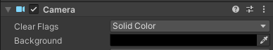
In order for passthrough underlay to be visible and properly occluded by in-app objects, the area which the passthrough underlay should be in transparent black (i.e. Color(0, 0, 0, 0)). To achieve this, you either have to use a shader similar to the one used by Multi Layer Underlays for Underlay Alpha Blending, or change the Main Camera background color to transparent black and set the Clear Flag to Solid Color.
Example of a Camera component with transparent black Background Color and Clear Flag set to Solid Color.
1-2-3. Unreal Passthrough Underlay
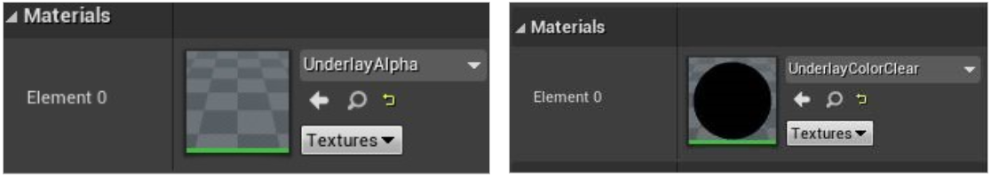
If you are an Unreal developer, here are the steps to apply passthrough underlay in your UE project. First, you need to show the Underlay in a specified area. For example, you can use a sky sphere mesh to show it in the background.
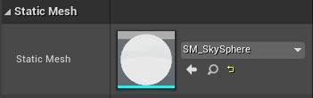
Create two static mesh components with the sky sphere mesh. And applying both materials below for each component to let the background transparent.
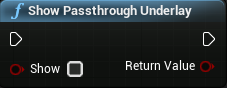
Use this blueprint to show or hide the passthrough underlay:
2. Rendering performance for MR
Sustaining a steady frame rate is essential for a great user experience in MR (Mixed Reality) applications. Even a slight juddering of images caused by a sudden drop in frame rate may make users feel nauseous. Optimizing the content performance is thus important for providing an enjoyable experience.
2-1. Why is the system busier in MR scene?
VIVE XR Elite supports high-resolution color passthrough. Compared to the VR scene, the MR scene consumes the extra CPU/GPU resources to process the camera image correction and compose the camera image with content scene to present on display.
2-2. Design concept for MR scene
As described above, here are some key factors that you have to considerate for MR scene design.
- DO NOT design too complex scene for MR since system also acquires GPU resource for passthrough image correction. Try to simplify your virtual objects as possible as you can.
- DO NOT use multi-layers unless you really need it since the content already got a passthrough image layer under the content layer. If the layer counts too more, the performance impact will be huge. Even you really need it, limit using 1 layer at most in your scene.
- DO NOT design the time-critical tasks that rely on real-time CPU utilization in your content since your task may be preempted by system threads with higher priority.
2-3. What approach we recommend
First, diagnosing the performance bottleneck of your content is CPU bound or GPU bound. There are some tools that can help you to clarify.
- The Unity Profiler and the Unreal Profiler are useful tools if you use Unity/Unreal engine to develop contents.
- For detailed performance analysis, you can use Android system tracing .
- Qualcomm Snapdragon Profiler: Identify application bottlenecks.
2-3-1. For the CPU bound case
There are many factors that could cause the CPU bound, including too many draw calls, complex calculations, etc. To determine whether your app is CPU bound or not, please don’t use the real-time CPU utilization as indicator of the CPU bound app since it is not reliable. Suggest checking the CPU total execution time of related rendering threads in a frame by the profiler tools mentioned above. If total time exceeds a half frame time, although it not over a frame time, it could compress the draw time that GPU can use. You should find out what functions take most and reduce its execution time as possible as you can.
2-3-2. For the GPU bound case
Wave SDK offers some useful features to balance image quality and GPU performance to mitigate GPU consumption of your content. Here are the methods that will impact GPU performance on the system or content side. To optimize GPU performance, we recommended tuning by this order.
| METHODS | CONSIDERATION |
|---|---|
| PASSTHROUGH IMAGE QUALITY | Trade-off between passthrough image quality and GPU resources. |
| ADAPTIVE QUALITY MODE | Comply system adaptive throttling policy to balance performance, power consumption, and frame quality. |
| FOVEATION MODE | Trade-off between content frame peripheral quality and GPU resources. |
| DISPLAY REFRESH RATE | Trade-off between frame latency and GPU/CPU resources. |
| FRAME SHARPNESS ENHANCEMENT | Trade-off between frame sharpness and GPU resources. |
2-3-2-1. Adjust the quality of passthrough image
Wave SDK offers WVR_SetPassthroughImageQuality API to allow the content adjust the quality of passthrough image for performance tuning. The passthrough quality would be changed after the method called, please determine the balance of the passthrough image quality and render performance qualified for your demand.
There are 3 levels that can be configured as below :
- WVR_PassthroughImageQuality_DefaultMode - suitable for the MR content without the specific demand.
- WVR_PassthroughImageQuality_PerformanceMode - suitable for the MR content that needs more GPU resource for virtual scene rendering.
- WVR_PassthroughImageQuality_QualityMode - suitable for the MR content that allows the users see the surrounding environment clearly, but the virtual scene of content must have the more fine tuning for performance.
- Native mehtod
bool WVR_SetPassthroughImageQuality(WVR_PassthroughImageQuality quality);
- Unity mehtod
// C#
Interop.WVR_SetPassthroughImageQuality(WVR_PassthroughImageQuality.PerformanceMode);
- Unreal methomd
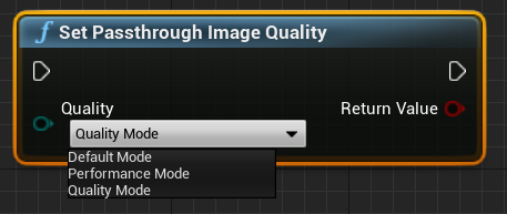
2-3-2-2. Adaptive quality and foveation Mode
Adaptive Quality Mode can automatically balance performance by adjusting GPU/CPU performance level, rendering resolution and foveation level. You can start with Performance-Oriented Mode. If the content does not have head-lock overlay, you may gain more performance while HMD is moving by dynamic Foveation Mode. You must set AQ to custom mode and turn off auto foveation, then set foveation mode to Dynamic manually.
2-3-2-3. Adjust the display refresh rate
Wave SDK offers WVR_SetFrameRate API to make the content set the display refresh rate for content tuning performance. The trade-off is higher refresh rate with better frame smoothness but heavier system loading; lower refresh rate with lighter system loading but worse frame smoothness. Currently VIVE XR Elite offers 90Hz and 75Hz for content selection.
- Native mehtod
// Get all available frame rates in this device.uint32_t frameRateCount;
WVR_GetAvailableFrameRates(0, &frameRateCount, nullptr);
If (frameRateCount > 0) {
    uint32 availableFrameRates[frameRateCount];
    WVR_GetAvailableFrameRates(frameRateCount, &frameRateCount, availableFrameRates);
}
// List all available frame rates in this device.
for (int i = 0; i < frameRateCount; i++) {
    LOGI("Available frame rate %d", availableFrameRates[i]);
}
// Set frame rate to 75.
for (int i = 0; i < frameRateCount; i++) {
    if (availableFrameRates[i] == 75) {
        WVR_SetFrameRate(75);
    }
}
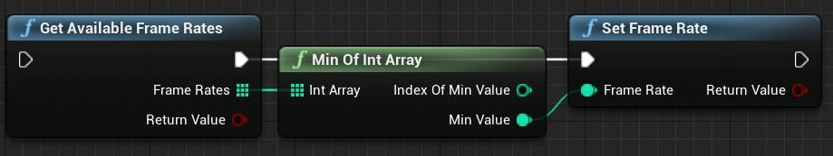
- Unity mehtod
Call:
Interop.WVR_SetFrameRate(75);
See Framerate .
- Unreal methomd
2-3-2-4. Frame sharpness enhancement
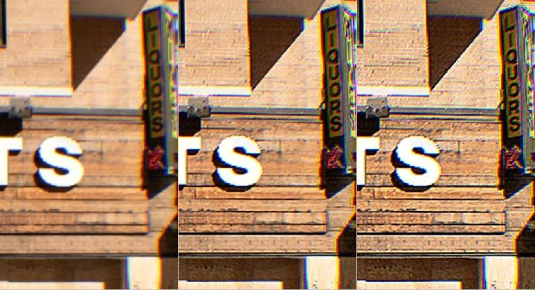
Frame Sharpness Enhancement(FSE) provides sharpen result by cost about more GPU usage. You can adjust FSE’s level to get best vision result to fit the rendering scene you like.
3. Alignment of virtual object and passthrough
On VIVE XR Elite, we reconstruct the single high-resolution color camera image into stereo passthrough frame for MR rendering. By doing so, the perspective of passthrough could match the user’s field of view. With correct perspective, the virtual objects will be placed in the right position and make user feel more naturally in mixed reality.
3-1. Why misalignment?
Our approach of passthrough (reconstruction with depth data) is mainly based on visual clues, supplemented by depth sensor. In some conditions, the virtual objects might not align with the environment properly, such as places at a distance, places that pretty close to viewing place, or user is facing a messy area. These misalignments might cause the user to feel uncomfortable and impact the MR experience.
3-2. Design concept for MR scene
For better MR experience, you should place or interact virtual objects in such condition:
- Floor, which has been well defined in RoomSetup stage.
- Furniture, such as user’s table or chair, obvious object with lots of depth clue.
- Drawing or books, easy to place and track.
- User-defined plane or objects.
To avoid misalignment, you should not place or interact virtual objects in such condition:
- Place in less than 0.5 meter or farther than 3 meters from viewing position.
- Messy areas without any empty space, the depth data will also be messed up.
- A plain lack of visual clue, such as white wall without anything hang on it.
3-3. What approach we recommend
Wave SDK offers WVR_SetPassthroughImageFocus API to allow the content adjust the focus mode of passthrough image. There are 2 focusing modes of passthrough in Wave SDK:
- WVR_PassthroughImageFocus_Scale - suitable for the MR content that prefers the user using hand or controller near interaction with virtual objects
- WVR_PassthroughImageFocus_View - suitable for the MR content without near interaction with virtual objects
If your design is aimed at interacting virtual objects with hand or controllers, such as placing on palm or treating controller as tools, most of time the user must focus on hand or controller. In this situation, we recommend you to set the focusing mode of passthrough as WVR_PassthroughImageFocus_Scale for correct scale of hand and controller.
If your design is aimed at viewing actual/virtual objects in surrounding, such as painting on the wall, furniture on the ground, character in a distance. In the case, user is mainly observing things, we recommend you to set the focusing mode of passthrough as WVR_PassthroughImageFocus_View for smoothing and comfortable MR experience.
Note
Since the 5.2.1 WaveSDK, the default mode has been changed from WVR_PassthroughImageFocus_Scale to WVR_PassthroughImageFocus_View.
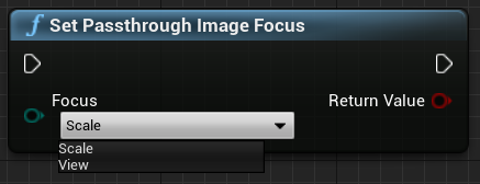
- Native mehtod
bool WVR_SetPassthroughImageFocus(WVR_PassthroughImageFocus focus);
- Unity mehtod
// C#
Interop.WVR_SetPassthroughImageFocus(WVR_PassthroughImageFocus focus);
- Unreal methomd
4. Scene perception (Beta)
4-1. What’s scene perception?
The scene perception is the system ability to percept environment objects like floor, ceiling, wall, desk, couch, door, window etc. The MR content which included scene elements can recognize those scene objects and interact with them to make player to immerse in the real world. Scene elements are defined as Plane 2D, Anchor, Scene mesh, and Object 3D.
- Plane 2D: support vertical/horizon plane and plane mesh
- Spatial Anchor: A coordinate marker in virtual space. Anchoring and tracking virtual objects to real world positions and orientations.
- Scene mesh: support visual mesh and collider mesh for room.
- Object 3D: support object in cube
For anchor, See 4-4. What’s Spatial anchor section for more infomation.
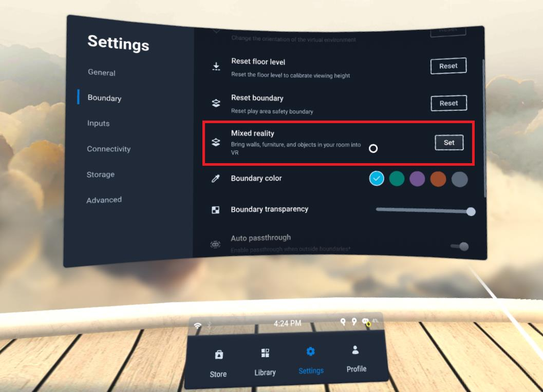
4-2. How to create planes/objects on VIVE XR Elite?
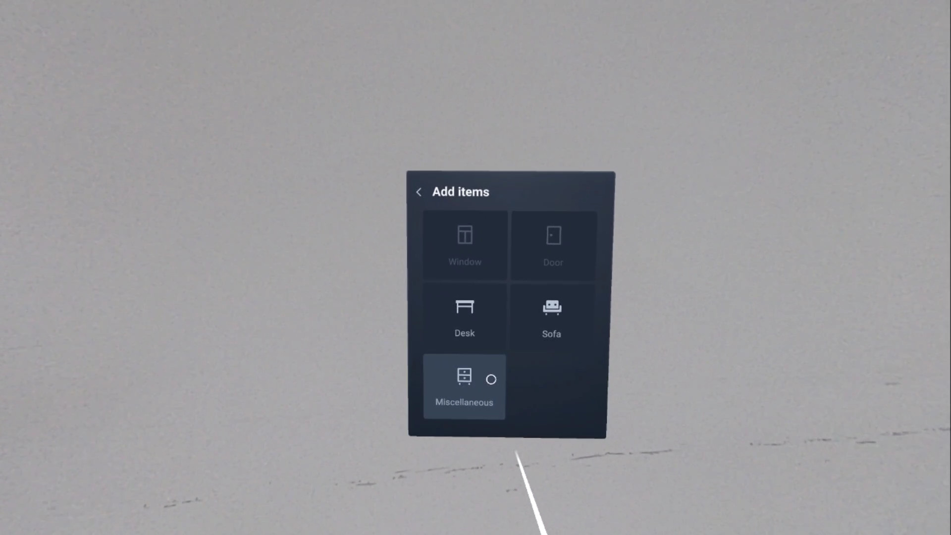
You can go Mixed reality in Settings to create and edit planes or objects.
Select Miscellaneous for Object 3D.
4-3. Lifecycle of scene perception elements
On current released, Plane, Object and Scene Mesh are all attached to the SLAM tracking map. For device which support multi-rooms, you will need to rebuild those scene perception elements when you move to new room and complete Room Setup.
The system will reload the related scene perception elements while suspend HMD and move to previous room. The attached Plane, Object and Scene Mesh will be destroyed once SLAM map of room been deleted.
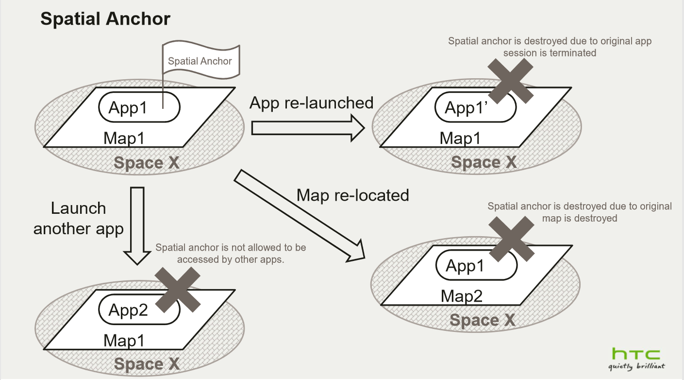
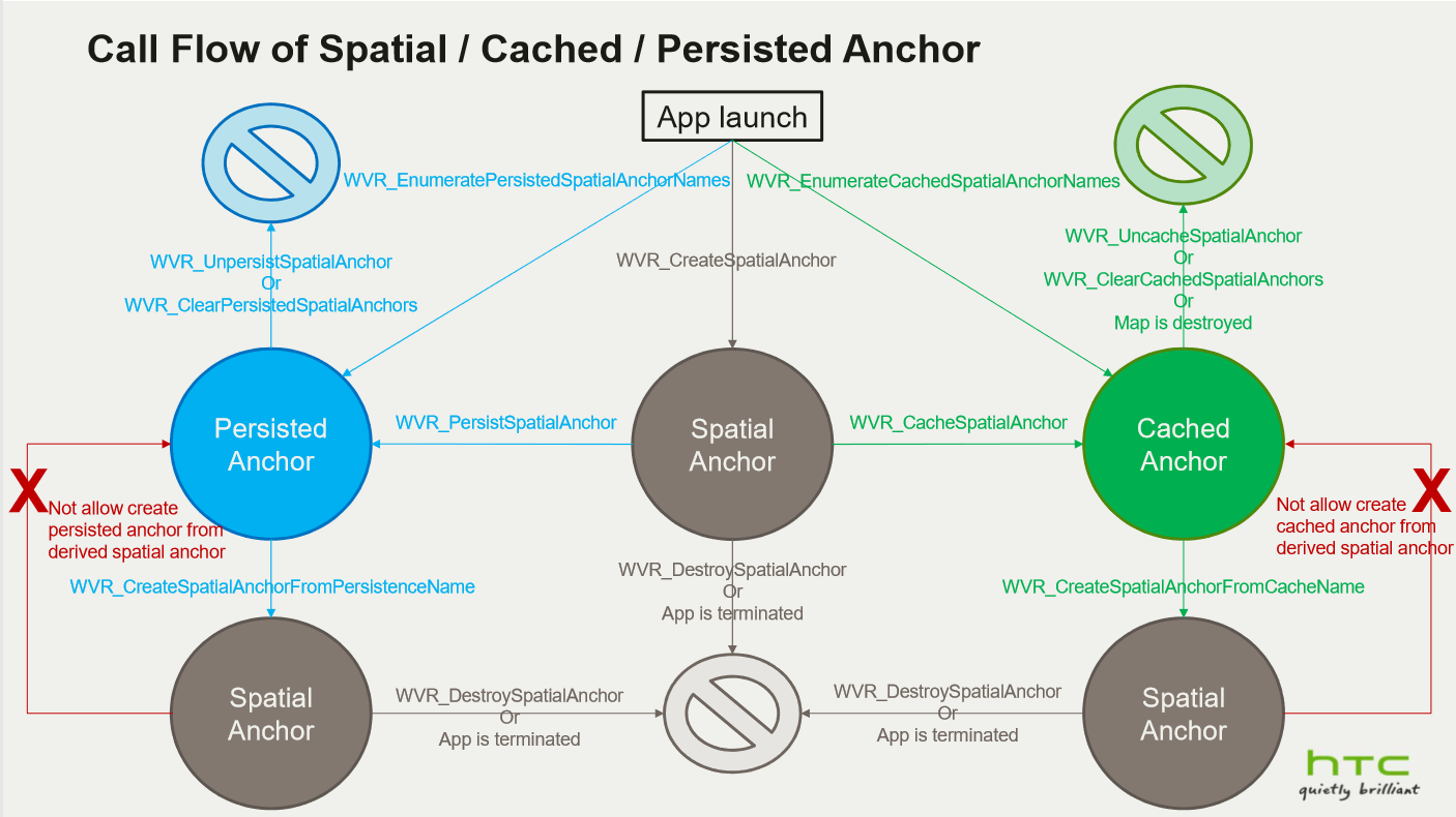
4-4. What’s Spatial anchor
- Spatial Anchor is a coordinate marker in virtual space, anchoring and tracking virtual objects to real-world positions and orientations. It servers as a bridge between virtual and augmented reality application, allowing for consistent object placement and tracking across different sessions and devices.
- Spatial anchor is represented an indicated location of tracking map within the space which user locates.
- Spatial anchor is created and destroyed by the application according to content design.
- Spatial anchor is destroyed when the application session is terminated or the tracking map is re-located.
- Spatial anchor can be stored as cached anchor or persisted anchor with a specified anchor name for reuse across application sessions.
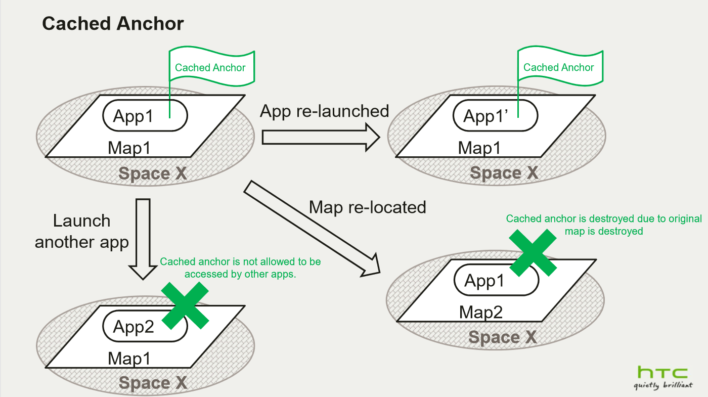
4-5. What’s Cached anchor
- Cached anchor binds to the current tracking map within the current space.
- Cached anchor can be enumerated after the application is re-launched but only the anchors with the current tracking map can be tracked.
- Cached anchor is deleted if the tracking map is re-located.
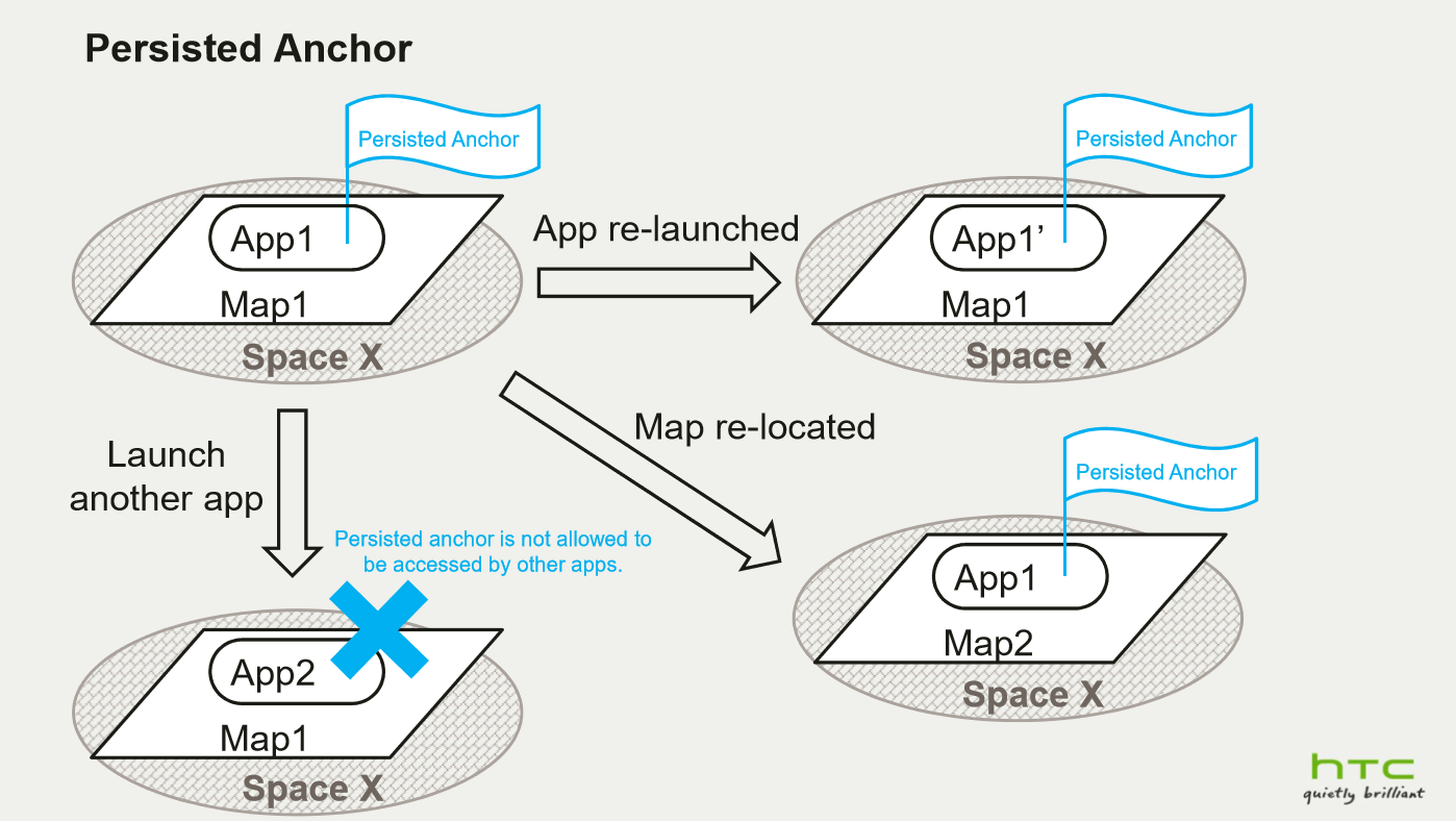
4-6. What’s Persisted anchor
- Persisted anchor can be recognized within the same space even the tracking map is re-located.
- Persisted anchor can be enumerated after the application is re-launched.
- Persisted anchor only can be deleted by the application.
4-7. life cycle of Spatial/Cached/Persisted anchor
4-8. Persisted anchor Export and Import
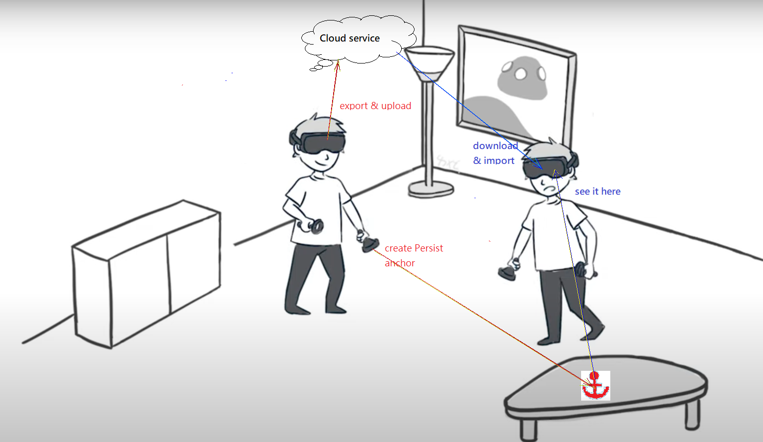
Persisted anchors can be shared with other HMDs for align coordinate origin or just for sync virtual object on the same place of real world. Your AP can export Persisted anchor data and upload it to Cloud, download it to other device then import it.
4-9. How to align virtual world in multi-user content
See Concept for Using Persisted Anchor in Multiplayer MR Games .
4-10. Persisted anchor usage guide
- Persisted anchor deployment:
- deploy your Persisted anchor on location with rich feature points environment
- walk closer to the place where you want to assign the Persisted anchor
- look around for a while to collect more feature points
- Usually you only need to deploy one Persisted anchor in your room, use this anchor to align other virtual objects
- remove none used Persisted anchors to save system resource
- It might be failed to create the Persist anchor since less feature points detected.
- Once failed to create the Persist anchor, you will not be able to enumerate, export or store it.
- Persisted anchor relocated:
- walk closer to the Persisted anchor
- look around and see the anchor’s location by different angle
- If anchor keeps relocating failed, try to walk through and look around your room.
4-11. Native development guide
4-12. Unity development guide
See Unity Scene Perception .
4-13. Unreal development guide
5. Trackable Marker (Beta)
5-1. What’s trackable marker
The trackable marker is the tracking ability to identify the specific defined pattern and transfer it to the marker’s location and orientation. This pose can later be applied as an anchor or aligned coordinate for multi-user in same room.
There are standard patterns like ArUco, QR code etc. We only support ArUco marker currently.
5-2. How to generate Aruco marker
The size of the marker affects its detectable distance, for scanning from further away, please generate a larger marker. The ArUco marker can be printed on papers or displayed on digital screens. Make sure there’s at least 2cm between the edge of the ArUco marker and the edge of the display medium.
To generate the detectable ArUco markers for this device, you can go to ArUco marker generator Web and select the compatible settings as below:
- For “Dictionary”, please only select 4x4.
- For “Marker ID”, pick one from 0~99.
- For “Marker size, mm”, please refer to the following section for setting a proper size.
Suggested marker size:
- When placing the marker on the floor, the marker size should be at least 17cm on each side, for an 170cm adult to detect the marker correctly.
- When displaying markers on a digital screen, make sure to lower the brightness and avoid reflecting. For a mobile phone with 6-inch screen, it is suggested to detect the marker in 0.6m.
- The detecting distance should not be larger than 10 times of the marker size to ensure the anchor’s precision. For example, a marker with size 17cm should be detected within 1.7m.
5-3. How to detect Aruco marker
The system can detect multiple markers with different marker ID as long as the markers are clearly visible in the environment.
Usually there’ll be a scanning stage for the system to detect the new ArUco marker. In this stage, make sure to observe the marker from different angle, the suggested method is to facing the center of the marker, then take a step to the left and right sides repeatedly, the marker should be detected in a few seconds.
5-4. How to track Aruco marker
Once the system detected the new ArUco marker, you can set it as a marker anchor, also known as a trackable marker. The info of the trackable marker will be remembered by system like the anchor until you delete it.
You can remove the marker print from your room and use it like an anchor. You can also move the marker print to a new place, watch the previous location to let system know it was removed then look at the new place to locate the new marker pose again.
5-5. Lifecycle of trackable marker
Each AP will maintain its own trackable marker, start tracking and stop tracking it. In scanning process, the tracking system will ignore trackable markers and only detect ArUco markers which has not been set as trackable marker yet.
You can also delete a trackable marker once you never used it anymore. Once you delete a trackable marker, you can scan it and set it as a trackable marker again.
5-6. Native development guide
5-7. Unity development guide
See Unity Marker .
5-8. Unreal development guide
See Unreal Marker .